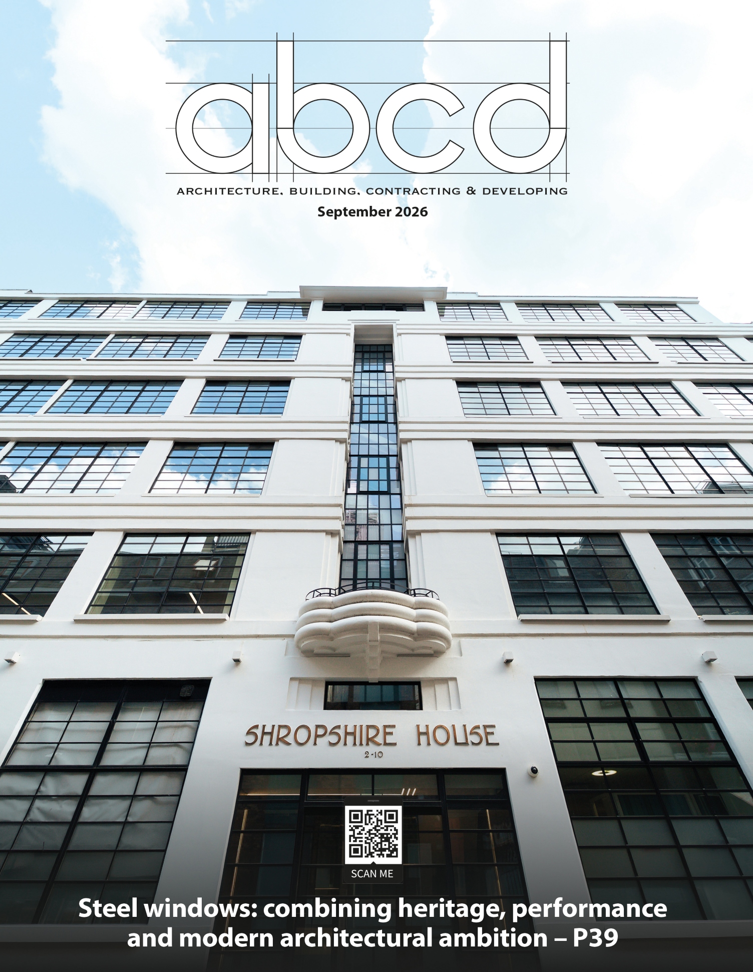
Open the literature for almost any façade system and the first thing you get is a photograph of a completed building on a good day. Low sun, clean glazing, a sky that has clearly been chosen. It is a handsome image and it answers precisely one question, which is what the material looks like when everything has gone right.
The specifier’s question is different. It is what happens at the corner. What happens where this system meets a different one. What the build-up is behind the visible face, in what order it goes on, and whether the tolerance at that junction is something a site team can realistically hit in November.
None of that is in the photograph, because a photograph of a finished building is by definition a picture of the moment after all the interesting decisions have been made.
What the hero shot is good for
It is worth being fair to it. The completed-project image does a real job. It establishes that the product exists at scale, it shows weathering and colour in daylight, and it gives a client something to look at when an architect is trying to explain a decision to a board.
Where it stops is the point at which somebody has to write it into a specification and somebody else has to build it. Neither of those people is looking at the face. They are looking behind it.
The four things that actually get asked
Sit in enough technical queries and the same handful come round.
How does this terminate. Not in the middle of a run, where every system behaves, but at a reveal, an external corner, a parapet, an opening. Most product failures a specifier has personally witnessed happened at a junction rather than in a field.
What is the full build-up. Substrate, breather, cavity, fixing, insulation, the visible layer, and crucially the sequence in which those go on. A section drawing gives it, but a flat section drawing asks the reader to hold four layers in their head simultaneously and infer the order.
What does the fixing look like once it is in. Concealed or exposed, and if concealed, what is holding it and how is it reached again in 15 years when something needs replacing.
And what does it look like at year three. Not year zero on a bright morning.
Why manufacturers started drawing rather than photographing
You cannot photograph most of that. The cavity is behind the cladding by the time there is anything to photograph, and site progress shots taken by whoever had a phone that afternoon are not a substitute for a considered explanation.
What has changed over the last few years is that a lot of building product manufacturers already hold accurate three-dimensional models of what they make, because the product was designed in CAD and the tooling was cut from it. Once that model exists, it can be opened up. A cutaway showing every layer at an external corner. An exploded view with the fixing pulled clear of the rail. A short sequence showing the order of installation, which answers in fifteen seconds a question that a section drawing and two paragraphs of text answer in five minutes if the reader is patient.

Studios that handle 3D rendering for construction materials generally work from those same engineering files rather than from a brief, which is the reason the output can be trusted dimensionally in a way a stylised illustration cannot. If the render shows a 25 millimetre cavity, it is because the model says 25.
That trustworthiness is the whole point. A specifier who suspects an image has been prettified will go and find the section drawing anyway, and the image has cost the manufacturer money for nothing.
The overlap with BIM that nobody planned
There is a quiet efficiency here that has caught a few manufacturers by surprise. The model that produces a cutaway for the technical brochure is closely related to the one that produces the BIM object, and both descend from the design file.

Firms that treat these as three separate jobs commissioned from three separate suppliers tend to end up with three versions of the product that disagree about something small, which is exactly the sort of discrepancy that surfaces at the worst possible moment. Firms that treat it as one model with several outputs do not have that problem, and the second and third outputs cost considerably less than the first.
What to ask for, if you are specifying
Ask for the corner. Ask for the junction with the adjacent system, not just with itself. Ask what the sequence is and whether there is a drawing or a sequence view showing it rather than a paragraph describing it.
If the manufacturer has a technical library, look at whether it contains details at the conditions your project actually has, or only the standard ones. A system with twelve beautifully drawn standard details and nothing at an inside corner is telling you something about where its problems are.
And ask what the model behind the images is. If it came from the design file, the dimensions in the render are the dimensions of the product. If somebody drew it afterwards to look right, they are not.
What to publish, if you are the manufacturer
Keep the hero shot. It has a job.
Then put the cutaway next to it, and the sequence after that. The specifier who is going to write your product into a document has already decided they like the look of it – or else the specifier would not be reading page four. What a specifier is doing on page four is looking for a reason to be confident – the fastest way to give a specifier one is to show them the part of your product that nobody photographs.
Everything that matters in a specification happens at the junction. It seems reasonable that the literature should go there too.